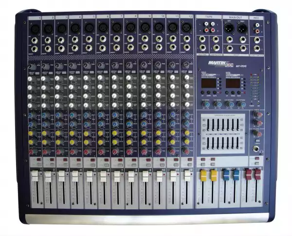
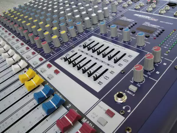
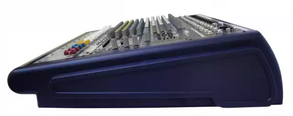
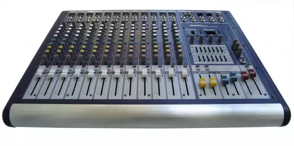
MARTIN WISMAN MF 1200
Garantiramo najni┼żu cijenu na tr┼żi┼ítu!
U slu─Źaju da prona─Ĺete isti proizvod po povoljnijoj cijeni,
molimo Vas da nas kontaktirate na:
info@player.hr
Highly accurate 12 segment Bargraph MetersINPUT CHANNEL SECTION1. BALANCE INPUT (MIC)Electronially Balanced inputs acceptable a standard XLR male connector. + 48V Phantom Power available on each input Mic socket, and this switch is on Rear Phantom Power.2. LINE INPUTThe unbalanced Mic input is provided for the use of an unbalance mic and is designed to accept an unbalanced high impedance input signal. (This use for connection Deck, Turntable, Keyboard etc..)3. INSERTThe INSERT is a break point in the input channel signal path. It allows the signal to be taken out from the mixer, through an external equipment such as a compressor, and then back to the mixer to continue the final mix output.4. TRIMThis has a function which adjusts the input sensitivity of each channel in order to input the constant level of the signal.5. LOW CUTSlide down the slide-switch, insert the 18 dB per octave 75Hz low cut filter in the signal path. This low cut filter is useful on live vocals to reduce stage rumble or "popping" from microphones. It can also be used to cut off low frequency hum.6. HIGHControl the high frequency tone of each channel. Always set this control to the 12 o'clock position, but you can control the high frequency tone according to the speaker, the conditions of listening position and listener's taste. Clockwise rotation of the control increases level.7. FREQUENCY + MIDThis equalization has a "bell" response i.e. having reached maximum amplification or attenuation at the selected frequency, the amplitude response returns to zero either side of that frequency. The FREQ at which this occurs is variable between 250Hz. The GAIN is variable between ±15dB at the selected frequency with a fixed q of 1.5Q is a factor a bandwidth. 8. LOWControl the low frequency tone of each channel. Always set this control to the 12 o'clock position, but you can control the low frequency tone according to the speaker, the conditions of listening position and listener's taste. Clockwise rotation of the control increases the level.9.AUX1.2This is normally derived after the EQ section and channel fader (PRE-FADER, POSE-EQ), and is therefore unaffected by the fader position and routing status. This makes the send particularly suitable for foldback or monitor feeds, which need to be controlled separately from the main P.A. Mix. All pre-fade sends may be selected internally to be PRE-FADER, PRE-EQ.10. EFX1.2This is normally derived after the EQ and channel fader (POST FADER, POST EQ), and is therefore follow any changers in fader level. They are normally used to drive effects processing units which are fed back into the mixer and which must fade out with the input channel.11. PANThe pan control sends continuously variable amounts of the post fader signal to either the left or right and G1 or G2 main busses. In the center position equal amounts of signal are sent to the left and right or G1 & G2 busses.12. STEREO (L-R)Push the switch, can use ST L-R fader.During the stereo L-R switch pushed, you can't use ST L-R fader.13. GRPS 1-2Push the switch, can use GROUP 1-2 fader.During the G1-2 switch pushed, you can't use stereo L-R fader.14. PEAKA red LED indicates a signal level at the insert return point, premaster fader, it illuminates at approximately 5 dB below clipping.15. CHANNEL FADERThis is function to adjust the volume of signal connection into each channel and adjust the volume of output, together with master fader. Normal operating position is at the "O" mark, providing 4dB of gain adove that point, if required. MASTER SECTION16. EFFECT PROGRAMSWhen adjust switch 17, 18, 19, 20 more effects are displayed.17. Pre-setPush more than 5 seconds, It automatacally memorize the displayed program number. Once Just Push M1. M2. M3. M4, always display memorized program.18. UP TAPE SWITCHOne push, one program up push with more than 5 seconds hi-speed program up.19. DOWN TAPE SWITCHOne push, one program down, push with more than 5 seconds, hi-speed program down.20. MUTEEffect ON/OFF.21. EFFECT STEREO (L/R)Depressing this switch, can let the EFFECT you need connect to the main control buses.22. EFFECT GROUP(1-2)Push the switch, can let the EFFECT you need connect to the main group buses.
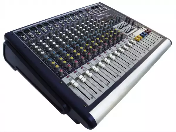
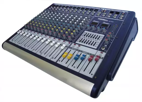
Ultra low noise 12 - Channel Mic / Line Mixer
- 12 Mono Input Channels with silver plated XLRs and balanced Line Inputs
- Ultra-low noise discrete Mic Preamps with +48 V Phantom Power
- Extremely high headroom - offering more dynamic range
- Balanced Inputs for highest signal integrity
- Ultra-musical 3-band EQ+FREQ on all mono channels
- Peak LEDs all Mono Channels
- 2 Aux Send per channel for external effects and monitoring
- 2X256DSP Digital of the effect system inside
- Separate Master Mix, Headphone Outputs
- 2-Track Inputs assignable to Master Mix
- Highly accurate 12 segment Bargraph Meters
INPUT CHANNEL SECTION
1. BALANCE INPUT (MIC)
Electronially Balanced inputs acceptable a standard XLR male connector. + 48V Phantom Power available on each input Mic socket, and this switch is on Rear Phantom Power.
2. LINE INPUT
The unbalanced Mic input is provided for the use of an unbalance mic and is designed to accept an unbalanced high impedance input signal. (This use for connection Deck, Turntable, Keyboard etc..)
3. INSERT
The INSERT is a break point in the input channel signal path. It allows the signal to be taken out from the mixer, through an external equipment such as a compressor, and then back to the mixer to continue the final mix output.
4. TRIM
This has a function which adjusts the input sensitivity of each channel in order to input the constant level of the signal.
5. LOW CUT
Slide down the slide-switch, insert the 18 dB per octave 75Hz low cut filter in the signal path. This low cut filter is useful on live vocals to reduce stage rumble or "popping" from microphones. It can also be used to cut off low frequency hum.
6. HIGH
Control the high frequency tone of each channel. Always set this control to the 12 o'clock position, but you can control the high frequency tone according to the speaker, the conditions of listening position and listener's taste. Clockwise rotation of the control increases level.
7. FREQUENCY + MID
This equalization has a "bell" response i.e. having reached maximum amplification or attenuation at the selected frequency, the amplitude response returns to zero either side of that frequency. The FREQ at which this occurs is variable between 250Hz. The GAIN is variable between ±15dB at the selected frequency with a fixed q of 1.5Q is a factor a bandwidth.
8. LOW
Control the low frequency tone of each channel. Always set this control to the 12 o'clock position, but you can control the low frequency tone according to the speaker, the conditions of listening position and listener's taste. Clockwise rotation of the control increases the level.
9.AUX1.2
This is normally derived after the EQ section and channel fader (PRE-FADER, POSE-EQ), and is therefore unaffected by the fader position and routing status. This makes the send particularly suitable for foldback or monitor feeds, which need to be controlled separately from the main P.A. Mix. All pre-fade sends may be selected internally to be PRE-FADER, PRE-EQ.
10. EFX1.2
This is normally derived after the EQ and channel fader (POST FADER, POST EQ), and is therefore follow any changers in fader level. They are normally used to drive effects processing units which are fed back into the mixer and which must fade out with the input channel.
11. PAN
The pan control sends continuously variable amounts of the post fader signal to either the left or right and G1 or G2 main busses. In the center position equal amounts of signal are sent to the left and right or G1 & G2 busses.
12. STEREO (L-R)
Push the switch, can use ST L-R fader.
During the stereo L-R switch pushed, you can't use ST L-R fader.
13. GRPS 1-2
Push the switch, can use GROUP 1-2 fader.
During the G1-2 switch pushed, you can't use stereo L-R fader.
14. PEAK
A red LED indicates a signal level at the insert return point, premaster fader, it illuminates at approximately 5 dB below clipping.
15. CHANNEL FADER
This is function to adjust the volume of signal connection into each channel and adjust the volume of output, together with master fader. Normal operating position is at the "O" mark, providing 4dB of gain adove that point, if required.
MASTER SECTION
16. EFFECT PROGRAMS
When adjust switch 17, 18, 19, 20 more effects are displayed.
17. Pre-set
Push more than 5 seconds, It automatacally memorize the displayed program number. Once Just Push M1. M2. M3. M4, always display memorized program.
18. UP TAPE SWITCH
One push, one program up push with more than 5 seconds hi-speed program up.
19. DOWN TAPE SWITCH
One push, one program down, push with more than 5 seconds, hi-speed program down.
20. MUTE
Effect ON/OFF.
21. EFFECT STEREO (L/R)
Depressing this switch, can let the EFFECT you need connect to the main control buses.
22. EFFECT GROUP(1-2)
Push the switch, can let the EFFECT you need connect to the main group buses.


